Latent heat thermal energy storage (LHTES) for low-temperature, mainly domestic hot water applications
Latent heat thermal energy storage (LHTES) is a type of energy storage technology that uses an energy source to heat and store thermal energy in a medium such as water, a phase change material (PCM), or a combination of the two. The thermal energy is stored as latent heat, which is released when the material is cooled. This type of energy storage has the potential to be used in a variety of applications, including heating and cooling systems, solar thermal power plants, and grid-scale energy storage. The main advantages of LHTES are its high energy density, low cost, and low environmental impact. Additionally, it can store energy for long durations, allowing for more efficient use of energy sources.
A schematic diagram of an LHTES conventional system can be viewed here. (1*) The storage component consists of a serpentine tube immersed in the Phase Change Material (PCM), a sort of paraffin wax. The whole paper can be read here.

(1*) Small Smart Sustainable Systems for future Domestic Hot Water (4S-DHW) by Mohamed Fadl, Philip C. Eames; Centre for Renewable Energy Systems Technology (CREST); Loughborough University Loughborough (Leicestershire) LE11 3TU, United Kingdom
Latent Heat Thermal Energy Storage (LHTES) has a wide range of potential engineering applications. It has recently gained considerable attention for space heating and cooling due to environmental concerns and the rising cost of fossil fuels (this just happened these days).
Phase Change Materials (PCMs) have the advantage of high thermal energy storage density, resulting in smaller store sizes; the potential for the near-constant temperature of operation can result in improved efficiency compared to a sensible heat storage system.
Many non-toxic PCMs are available with melting temperatures covering a wide range of applications. These features make PCMs an attractive option for many applications, for example, passive temperature control of buildings, compact thermal energy storage systems, medical applications requiring constant temperature, storage of recovered industrial waste heat for later use, and temperature control of electronics. The complex nature of the PCM melting-solidification process and the combined conductive and convective heat transfer processes within the PCM are of continuing interest.
Latent Heat Thermal Energy Storage (LHTES) is a promising technology for storing heat energy as a phase change material. However, there are several disadvantages associated with its use.
First, LHTES systems are expensive to install and maintain. They require large amounts of capital investment to build the necessary infrastructure and purchase the necessary materials. Additionally, the materials used in LHTES systems are often costly and difficult to obtain.
Second, LHTES systems are not as efficient as other forms of energy storage, such as batteries. They cannot store as much energy as other technologies, meaning they will require more energy to operate.
Third, LHTES systems can be difficult to control and operate. These systems are often complex and require significant expertise to handle them correctly.
Finally, LHTES systems are limited in terms of the temperatures they can store energy at. This limits their potential applications, as they cannot be used in applications requiring higher temperatures.
But the real significant disadvantages are in the heat transfer mode during charge and discharge cycles. These are presented below.
- Charge and discharge cycles are performed with different fluids that flow alternately through the same coil immersed in the PCM mass. When the discharging fluid is introduced into the same coil through a set of valves, the PCM mass solidifies, and when the charging fluid flows through the coil, the PCM mass melts.
- The PCM melting-solidification process occurs through the combined conductive and convective heat transfer processes within the PCM (*1). During the charge phase, the PCM first melts on the Heat Exchanger (HX) surface, and then, under the influence of free convection heat transfer, the liquid-solid interface moves to the rest of the PCM mass. During the discharge phase, the PCM first solidifies on the HX surface, and then the solid-liquid interface moves to the rest of the PCM mass by conduction only. In this way, there is a significant discrepancy between the charge and available discharge power. The almost total absence of free convection during the discharge phase of the PCM is a major issue for current conventional LHTES systems. This issue cannot be solved with any traditional techniques.
Introducing the innovative concept of heat pipes can remove or significantly diminish the issues “a” and “b” as described below.
- The unique (possibly patent) heat pipes act simultaneously in the three chambers to transfer the heat between them. Please take a look at this schematic diagram. When the CHARGING FLUID flows through the heat pipes in the chamber for the thermal energy charging phase, the heat pipes simultaneously transfer the energy to both the PCM thermal energy storage chamber and the discharging energy chamber. If the DISCHARGING FLUID doesn’t flow, the energy will only be stored in the PCM chamber. When the CHARGING FLUID stops flowing, the PCM thermal store chamber instantly becomes the heat source, and the heat pipes transfer the stored energy to the DISCHARGING FLUID. In this way, there is no need for charging and discharging fluids to flow alternately through the tubes of the same Heat Exchanger (HX). Research is needed to get the optimum amount of working fluid for the heat pipes and to design the wick geometry.
- Every heat pipe in the bundle is isothermal on its entire length. Accordingly, the heat flux is the same over the whole heat pipe length.
- For research needs, every heat pipe in the bundle can be fitted out inside with a capillary tube for a thermocouple installation. Please look here for a schematic diagram (heat pipes for a roto-molding application) or here for the corresponding photo.
- Regarding the above issue labeled “b,” there is no method to avoid the solidification of PCM material on the conventional HX surface during when discharging phase. But using a unique flat system based on heat pipes (possible patent), we can cut the PCM material in thin slices and minimize in this way the thickness of the PCM mass where the heat transfer occurs by conduction only.
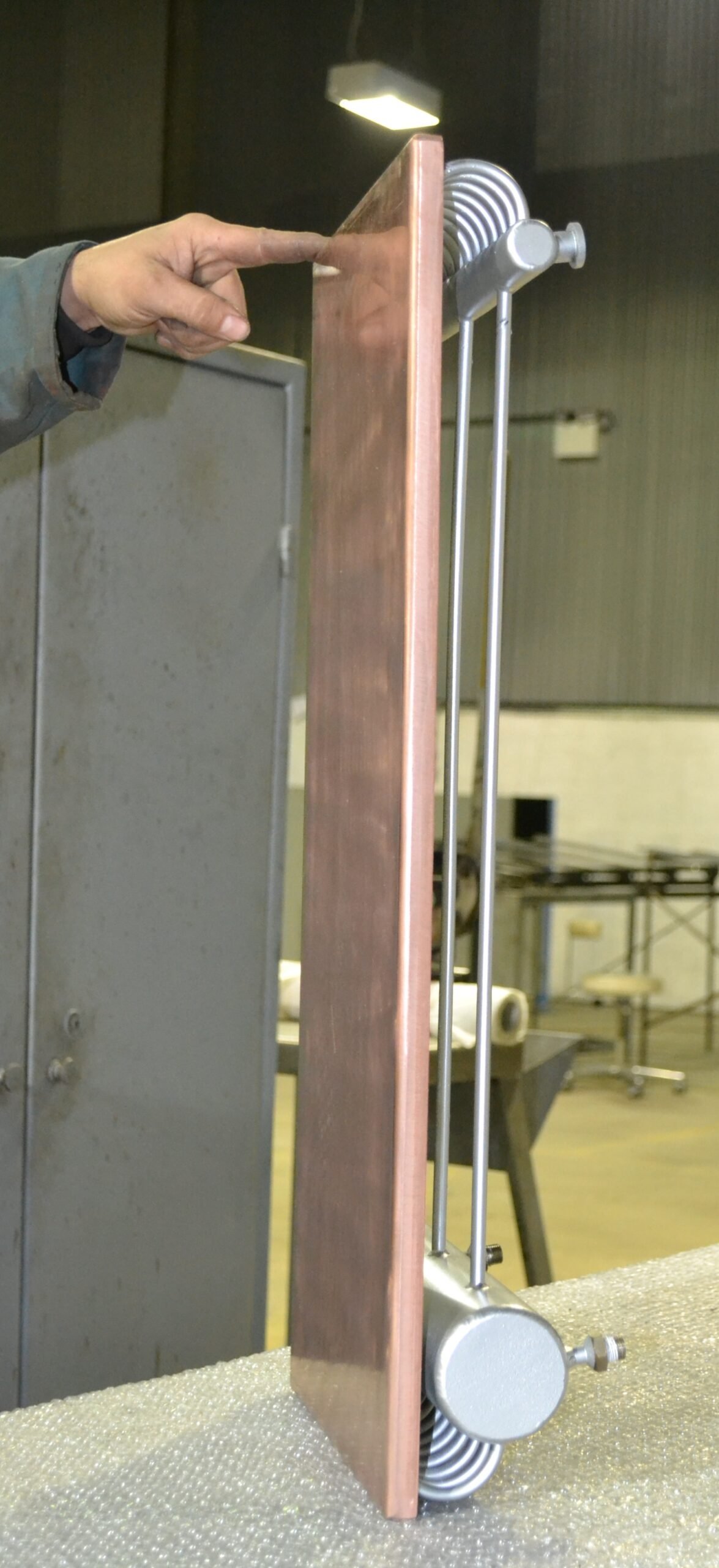
- An introduction is needed at this stage. Two identical sheets of copper (about 400 x 600 mm, #5 mm) are heated for 2 minutes each with the same large torch. The copper sheet on the right gets very hot (above 380 C) after 2 minutes of heating. After the same 2 minutes of heating, the copper sheet on the left is still cold, and the worker can put his hand on it. The copper sheet on the left is a flat heat pipe-based system. Please look at the video to see what a flat heat pipe-based system can do. Watch the video here. What is behind the copper sheet on the left can be seen in these photos here, here, and here.
- To diminish the influence of conduction heat transfer and consequently diminish the issue of PCM solidification on the HX surface, we suggest two types of flat systems based on heat pipes.
- Type 1. Copper water-independent heat pipes soldered on a copper plate in the chamber for the thermal energy storage phase and free in the other two chambers. For the experiment described in *1, the overall thickness of the flat assembly inside the PCM chamber could be a maximum of 9 mm. Many of these flat assemblies cut the PCM mass in convenient slices. We are sure that this flat heat pipe system concept will significantly improve the discharge power vis-a-vis the conventional heat exchangers. Please find here a self-explanatory schematic diagram.
- Type 2. Special flat heat pipe made in the form of a vacuum chamber. Like Type 1 above, these flat heat pipes cut the PCM mass in convenient slices. For the experiment described in [*1], the overall thickness of this flat heat pipe inside the PCM chamber could be a maximum of 5 mm. Please find here s self-explanatory schematic diagram.
- When designing both of the above versions, the possibility of extending the heat transfer surfaces by finning will be considered.



[*1] – Fadl, Mohamed, and Philip C. Eames. 2019. “An Experimental Investigations of the Melting of RT44HC Inside a Horizontal Rectangular Test Cell Subject to Uniform Wall Heat Flux”. Open Here.