

1. Temperature Difference: ∆𝒕
The temperature difference can be expressed as the difference between the mean temperatures of the two agents involved in the heat transfer process.
 – the temperature of the heat input agent at the inlet
 – the temperature of the heat input agent at the outlet
 – the temperature of the heat output agent at the inlet
 – the temperature of the heat output agent at the outlet
Therefore, the equation for the temperature difference can be expressed as:
3. Sodium heat pipe operating temperature: 𝒕𝒉𝒑
As shown in the previous chapter, the sodium heat pipes are auto-adjusting devices. In other words, the quantity of heat that enters or leaves the heat pipe determines its operating temperature. If the amount of outgoing heat exceeds that of incoming heat, the operating temperature of the heat pipe will decrease until the thermal balance is achieved. Conversely, if the outgoing heat is less than the incoming heat, the operating temperature will increase until a thermal equilibrium is attained again.
When vaporization and condensation sections have the same geometry and are exposed to identical heat transfer parameters, we can define the heat pipe operating temperature as follows:
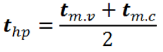
where:


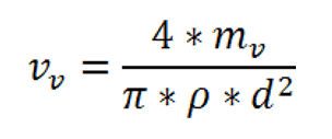
The following symbols will describe the velocity of sodium vapor within the heat pipe:
𝒱𝒱 – sodium vapor velocity inside the heat pipe [m/s]
𝓂𝒱 – the mass rate of sodium vapor [Kg/h]
𝒉 – Sodium vapors heat of vaporization corresponding to working
temperature [Kj/Kg]
𝑉 – Volumetric rate of sodium vapors corresponding to axial heat
transfer rate [m3/h]
ρ – Sodium vapors density corresponding to the heat pipe operating
temperature [Kg/m3]
𝑑 – Sodium heat pipe inner diameter [m]
Accordingly, the following equations will be utilized:

Finally:
As the figure above depicts, the sodium heat pipe can work in five different situations. We will now describe each of them.
In situation number 1, the sodium heat pipe operates in a stable mode. This implies that there is a thermal equilibrium in which the heat input to the heat pipe is equal to the heat output to the receiver. The consequence of this is that the operating temperature of the sodium heat pipe remains constant. Furthermore, it should be noted that the condensate layer at the end of the condensation section is very thin, and no liquid accumulation is present. A sodium heat pipe working in this situation can be seen here.

Situation number 2 is characterized by a thickening of the sodium condensate as it returns to the vaporization section. This change in the returning condensate thickness occurs due to increased sodium vapor velocity caused by increased heat transfer. The increased sodium vapor velocity leads to a higher friction force at the interface between the vapors and the returning condensate. Consequently, the flow of the returning condensate is impeded, causing the condensate layer to thicken. Although the sodium heat pipe continues to operate stably, the thermal equilibrium has begun to degrade. A sodium heat pipe working in this situation can be seen here

In situation number 3, the returning condensate layer thickness increases even further. As a result, some sodium liquid cannot return to the evaporation section and instead accumulates at the end of the condensation section. This leads to a decline in the performance of the sodium heat pipe, accompanied by a decrease in the operating temperature and the start of small metallic noises. A sodium heat pipe working in this situation can be seen in this video, where you can also hear the specific metallic noises of the sodium droplets hitting the end cap of the heat pipe. We hope you can distinguish the particular metallic noises of the sodium droplets from the background noise emanating from the workshop adjacent to the laboratory.
Situations numbered 4 and 5 are characterized by a further increase in the returning condensate layer thickness and an even greater retention of sodium condensate at the end of the condensation part due to a significant increase in the sodium vapor velocity. As a result, less and less sodium liquid is available for heat transfer in the vaporization part. This causes a dramatic decrease in the performance of the sodium heat pipe, ultimately leading to a phenomenon known as “burnout.” In the absence of a proper amount of sodium in the vaporization section, the heat pipe cannot transfer enough heat, causing the temperature of this section to increase and ultimately leading to the destruction of the heat pipe due to an implosion. We do not have any photographs depicting a heat pipe in the situations above. However, the image presented here shows the appearance of a sodium heat pipe destroyed due to burnout.

As an additional point, it should be noted that there is no danger associated with the destruction of a sodium heat pipe in this manner. When this occurs, there is no explosion; the sodium burns with a small yellow flame.


